To properly test static control grounding points, you'll need to follow five essential steps. First, prepare your testing equipment, including a calibrated ground resistance tester and ESD meters. Next, establish reliable ground reference points with resistance under 10 ohms using single-point grounding methods. Then, measure surface resistance values (RTT and RTG) according to ANSI/ESD S4.1 standards. Fourth, inspect your static grounding clamps for proper functionality and clean contact surfaces. Finally, document all your measurements, including resistance readings and equipment conditions. Following these steps guarantees your facility's ESD protection meets safety standards and compliance requirements.
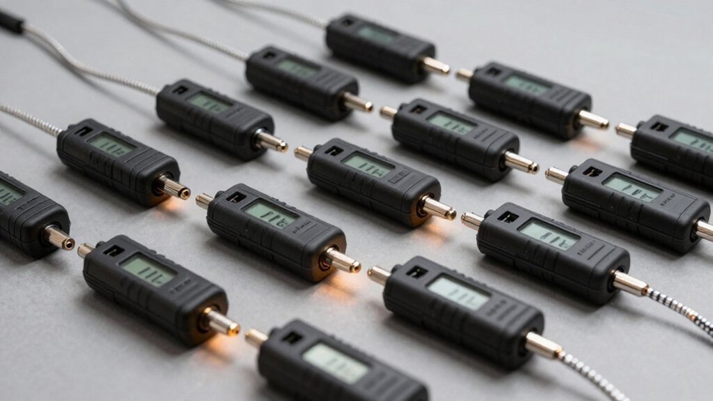
Test Equipment Preparation
Several critical pieces of test equipment are essential for properly evaluating static control grounding points. You'll need a ground resistance tester that's specifically designed for AC systems, as standard multimeters won't provide reliable readings.
You'll also want to include a grounding analyzer to verify your wiring configuration meets National Electrical Code requirements and detect any system flaws. The total system resistance including the person and garment must be less than 3.5 megaohms for effective ESD control.
Before testing, verify all your equipment is properly calibrated according to manufacturer guidelines and industry standards like ANSI/ESD S6.1 and NFPA 77. Check the calibration dates and maintain detailed records of previous calibrations.
If you haven't calibrated your equipment recently, do so before proceeding with any tests.
Don't forget to inspect your test equipment for signs of damage or malfunction. You'll need to verify that your ground impedance tester can effectively inject AC current between the equipment-ground and neutral conductors.
For workstation testing, make sure your ESD testers, including wriststrap testers, are functioning correctly. If you're using clamp-on ground testers, confirm they can properly induce voltage and measure current flow to calculate impedance accurately.
Establish Ground Reference Points
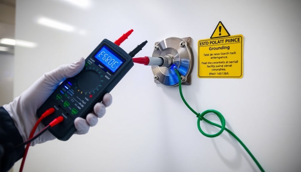
Identifying proper ground reference points lies at the heart of any effective static control system. You'll need to select points that provide a direct path to earth with minimal resistance, focusing on metal components that offer less than 10 ohms of resistance. Make certain your chosen points are clean, free from corrosion, and maintain continuous conductivity.
For ideal performance, you'll want to implement a single-point grounding system, as it helps maintain a consistent zero potential reference and minimizes potential differences between equipment. Dedicated static grounding rods should be tested regularly to maintain effectiveness.
When you're verifying your ground points, use the Fall of Potential method for accurate resistance measurements, or opt for the Simplified version in tight spaces.
You'll need to regularly inspect and maintain your grounding system to guarantee its effectiveness. Check all clamps and connections for wear, and keep the system free from dirt and damage. If you're integrating with control systems, you can install visual indicators like LED lights to verify connection status.
Remember to follow proper procedures – always clamp on first and remove last. For RF subsystems, you might consider multi-point grounding, but stick to single-point grounding for low-frequency applications to maintain system integrity.
Measure Surface Resistance Values
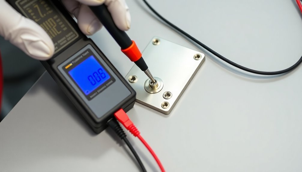
In accordance with ANSI/ESD S4.1 standards, you'll need to measure both RTT (Resistance Top-to-Top) and RTG (Resistance-to-Groundable Point) values to verify your surface's ESD protection capabilities.
Start by clearing the test area of any ESD-sensitive devices and guaranteeing the surface is clean and dry. Static dissipative materials provide effective ESD protection with resistance values greater than 1 x 10^6 ohms.
For RTT measurements, place two 5-pound electrodes on your surface, positioning them 10 inches apart and at least 2 inches from any edge.
For RTG testing, attach the black test lead to your established ground point and position one 5-pound electrode on the surface. Press and hold the test button on your ESD meter until you get a stable reading.
Your surface resistance measurements should fall within the static dissipative range of 1 x 10^6 to 1 x 10^12 ohms to provide adequate ESD protection.
Remember that environmental conditions like humidity and temperature can affect your readings, so you'll want to maintain consistent testing conditions.
Always use calibrated equipment to guarantee accurate measurements, and document both RTT and RTG values for compliance verification.
If your readings fall outside the acceptable range, you'll need to investigate potential issues with your surface or grounding connections.
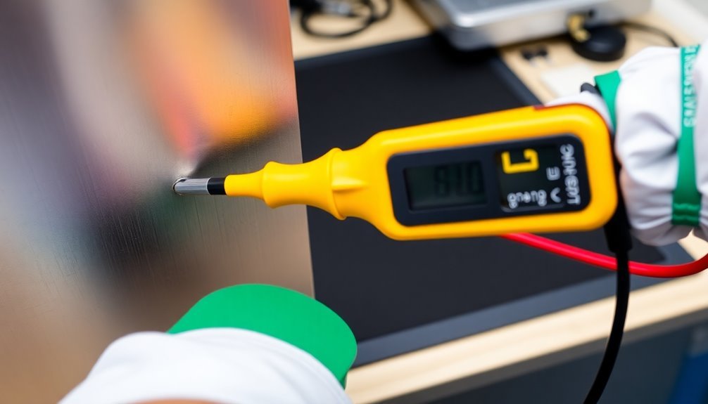
Static Grounding Clamp Inspection
Through proper inspection of static grounding clamps, you'll guarantee reliable ESD protection in both hazardous and non-hazardous environments. Start by examining the clamp's intrinsically safe design features, paying special attention to the pulsing LEDs that provide visual verification of proper grounding connections. Operating across temperatures from minus 40 to 140°F, these clamps maintain consistent performance in diverse environments.
You'll need to test the grounding circuit resistance by clamping directly onto the grounding conductor. Make sure the jaw mating surfaces are clean and unobstructed for accurate measurements. When testing, verify that you've established a complete electrical circuit with the earth included in the return loop. Check for any signs of high resistance bonds or poor electrodes that could compromise safety.
When inspecting static grounding clamps in specific applications, such as utility poles or pad-mounted transformers, you'll need to account for multiple parallel ground connections. For cell tower installations, be careful not to measure loop resistance instead of ground system quality.
Document your inspection by recording the date, ohms reading, and pole number. Don't forget to verify the battery condition, as these clamps rely on battery power for extended operation in both indoor and outdoor settings.
Record and Document Results
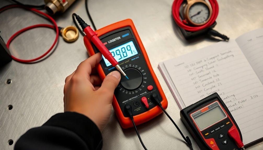
Proper documentation of static control grounding points requires four essential measurements you'll need to record: resistance top-to-top (RTT), resistance-to-ground (RTG), wrist strap readings, and foot grounder values.
When testing ESD worksurfaces, record your RTT and RTG measurements using an ESD meter kit, ensuring they're below 1 x 10e9 ohms for RTG tests. Document the date, time, and specific equipment used for each measurement. Regular testing schedules are essential due to potential wear and degradation of ESD equipment over time.
For wrist straps, you'll want to record resistance readings below 3.5 x 10^7 ohms, while foot grounders should measure less than 1 x 10^9 ohms.
Don't forget to document your metallic grounding system measurements, which should be less than 10 ohms according to NFPA 77 standards. You'll need to note the condition of all grounding connections, verifying they're tight and corrosion-free. Keep track of any visual indicators or interlocks you're using to monitor ground connections.
Store all your documentation in an easily accessible location for audits and inspections. Update your records regularly to reflect any changes in equipment or grounding configurations, and maintain certification records for all grounding systems and equipment.
Frequently Asked Questions
How Often Should Static Control Grounding Points Be Recalibrated?
You'll need to test your grounding points weekly or daily for wear, but complete calibration should occur quarterly per corporate procedures. Use continuous monitors and verify calibration units semi-annually following manufacturer's guidelines.
Can Multiple Grounding Points Be Connected to the Same Ground Electrode?
Yes, you can connect multiple grounding points to the same ground electrode through various methods like wires, clips, cables, or clamps. You'll want to guarantee that the electrode meets NEC requirements for resistance.
What Temperature Conditions Affect the Accuracy of Static Control Measurements?
You'll find that extreme temperatures affect your static control measurements considerably. Hot conditions can alter material properties and strain gauge accuracy, while cold temperatures impact electronic components and thermoelectric voltage readings in your measuring equipment.
Are Wireless ESD Monitoring Systems as Reliable as Wired Ones?
You shouldn't rely on wireless ESD monitoring systems as they're less reliable than wired ones. NASA studies show they fail to prevent charge buildup and don't meet ANSI/ESD S20.20 performance requirements.
How Do Humidity Levels Impact Static Control Grounding Point Effectiveness?
You'll find your grounding points work best at 45-55% humidity. Higher levels enhance conductivity and dissipation, while low humidity below 30% reduces effectiveness by making materials more insulative and static-prone.
In Summary
By following these 5 steps, you'll maintain a reliable static control system and protect sensitive equipment from ESD damage. Regular testing of grounding points is essential for workplace safety and quality control. Don't forget to keep detailed records of your measurements and immediately address any points that fail testing. Your diligence in following proper testing procedures guarantees continuous protection of valuable assets.


Leave a Reply