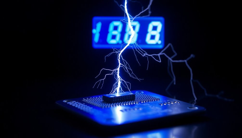
You can effectively monitor static discharge events through these 10 proven methods: Use an oscilloscope with high bandwidth settings to capture waveforms, implement contact discharge testing with ESD simulators, utilize air discharge testing following IEC standards, employ embedded sensors for real-time detection, set up automated data logging systems, conduct Human Body Model simulations, deploy field strength measurement tools, install continuous monitoring systems on I/O pads, perform calibrated simulator measurements, and integrate specialized ESD detection circuits. These techniques form the foundation of thorough ESD protection, but there's much more to explore about maximizing your monitoring effectiveness.
Air Discharge Testing Methods
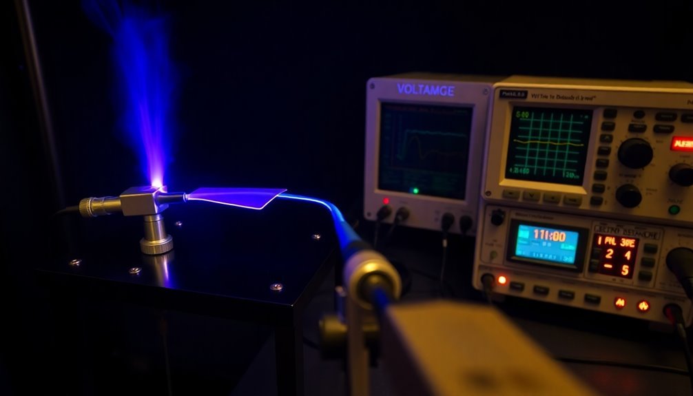
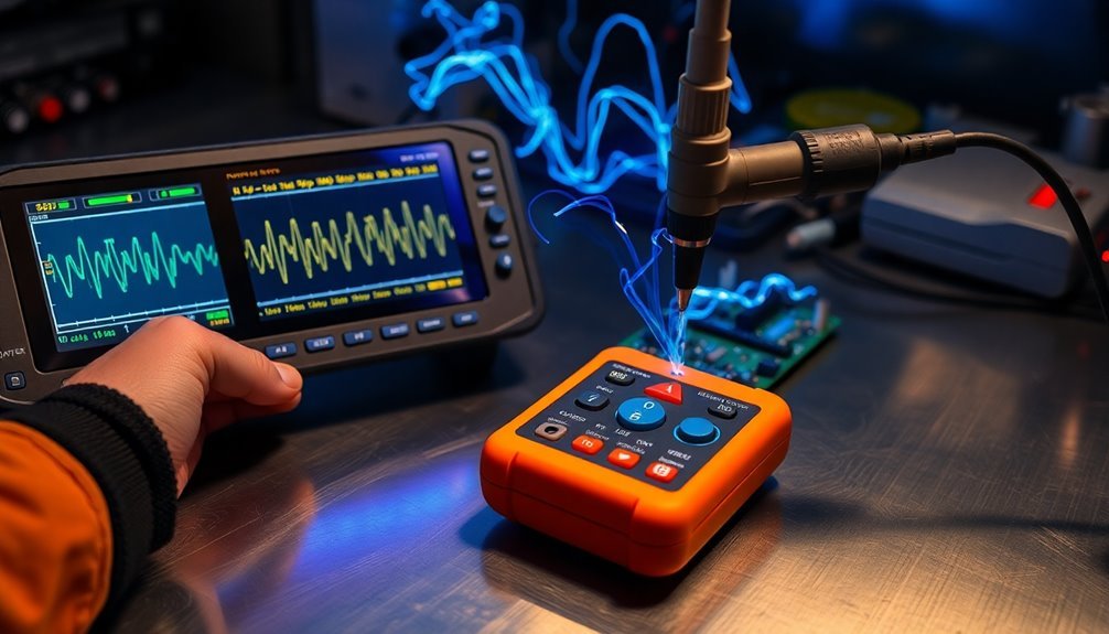
Air discharge testing forms a critical component of electrostatic discharge (ESD) verification, simulating real-world scenarios where static electricity jumps across air gaps. To perform this test, you'll need an ESD simulator with a rounded tip, which you'll bring close to the equipment under test (EUT) until a discharge occurs. The heat generated during discharge can potentially damage sensitive electronic components.
You must follow IEC 61000-4-2 standard specifications, which define four testing levels ranging from 2 kV to 15 kV. Start with the lowest test voltage and gradually increase it, applying at least 10 discharges for each polarity. Make sure you maintain a minimum one-second interval between discharges.
Your test setup should include a Ground Reference Plane (GRP) and both horizontal and vertical coupling planes for indirect discharges. You'll need to test all sides of the EUT, and remember that environmental factors like humidity and temperature can affect your results.
Air discharge testing typically shows higher uncertainties compared to contact discharge methods, but it's essential when contact testing isn't possible. Always guarantee your ESD gun's return lead connects properly to the GRP for accurate results.
Contact Discharge ESD Analysis
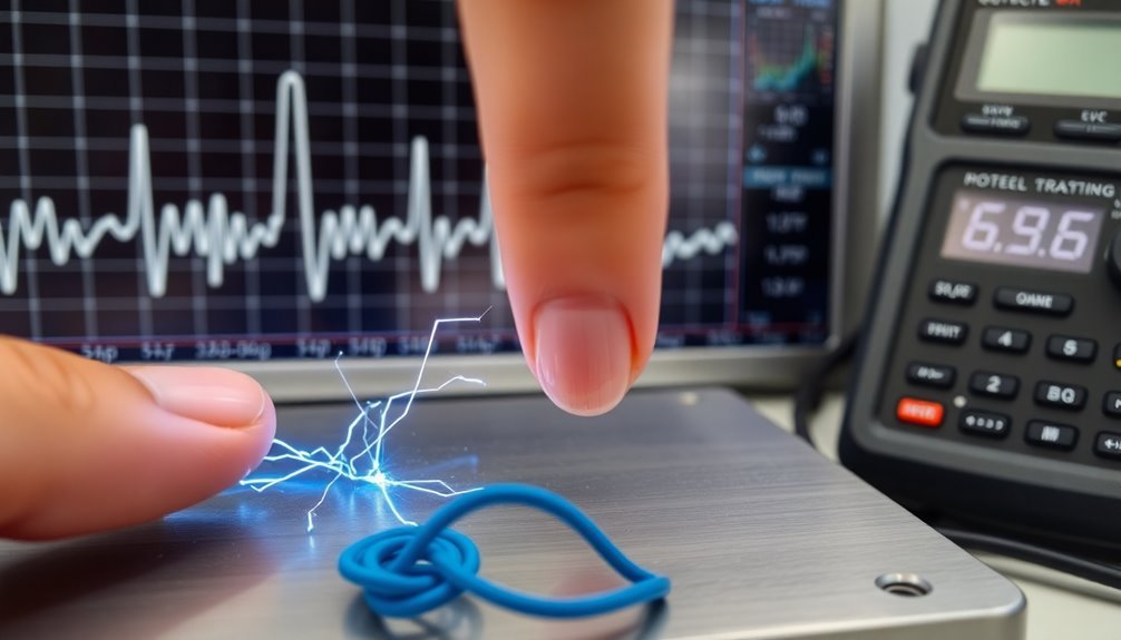
While air discharge testing simulates static jumps across gaps, contact discharge testing provides a more controlled and repeatable method for ESD verification.
You'll apply ESD stress directly to your Equipment Under Test (EUT) or to an adjacent coupling plane using specialized probe tips designed for contact discharge. The test probe tip should remain in direct contact with the test point throughout the discharge event.
To perform contact discharge testing, you'll need an ESD simulator equipped with proper probes and a well-bonded ground reference plane. You'll charge the simulator's capacitor to your required test level, typically ranging from 2kV to 8kV for commercial applications, before triggering the discharge through the probe tip to your EUT.
Your testing must comply with standards like IEC 61000-4-2, which specifies precise waveform characteristics including a 0.8ns rise time for contact discharge. You'll need to test both positive and negative polarities and verify current parameters at specific time intervals (30ns and 60ns).
When setting up your test environment, guarantee you're using appropriate coupling planes (HCP and VCP) and that your EUT has accessible conductive points for direct contact testing. This method's superior repeatability makes it the preferred choice for reliable ESD verification.
Human Body Model Applications
The Human Body Model stands out as the primary method for evaluating ESD sensitivity in electronic components. It is particularly valuable for classifying how sensitive devices are to electrostatic discharge, which directly impacts how you'll need to design your ESD control programs.
The model simulates what happens when you touch an electronic device, using a 100 pF capacitor and a 1.5 kΩ discharge resistor to replicate the human body's electrical characteristics. The discharge current follows a characteristic pattern with a rise time of 10 ns and continues for approximately 150 nanoseconds.
To effectively implement HBM testing in your monitoring strategy, consider these key applications:
- Device sensitivity classification to determine appropriate handling requirements and protection measures
- Protection circuit design validation to confirm your components can withstand common ESD events
- Automated testing sequences to consistently evaluate device functionality before and after ESD stress
When you're working with HBM applications, you'll need to understand that while it's incredibly useful for simulating human contact scenarios, it won't cover all possible ESD events. That's why you'll often need to supplement your testing with other models like MM and CDM for thorough ESD protection.
The standardized testing procedures in ANSI/ESDA/JEDEC JS-001 provide you with reliable frameworks for consistent evaluation across different devices.
ESD Waveform Monitoring Equipment
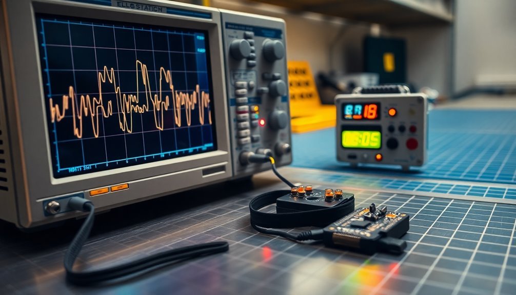
You'll need a high-bandwidth oscilloscope with at least 1 GHz capability to accurately capture ESD waveform characteristics and rise times.
When setting up your oscilloscope, configure the vertical sensitivity to 200-400 mV/div and set the time base to 20 ns/div for ideal waveform visualization. Testing should incorporate standard ESD models like the Human Body Model and Charged Device Model for comprehensive evaluation.
Your target probe must undergo proper calibration to maintain system accuracy within ±0.3 dB from DC to 1 GHz and ±0.8 dB from 1-4 GHz for reliable measurements.
Oscilloscope Setup Requirements
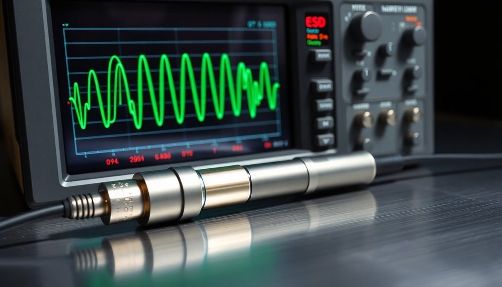
Proper oscilloscope setup plays a critical role in accurately monitoring ESD events. You'll need to select an oscilloscope with at least 4 GHz bandwidth and 10 Gsamples/s sampling rate to capture the fast-rising edges of ESD pulses effectively. Following IEC standards, the rise time requirements must fall between 0.6 to 1.0 nanoseconds.
Set your scope to single-shot mode with a positive-edge trigger, and adjust the vertical sensitivity to either 200 mV/div or 400 mV/div based on your simulator voltage.
To achieve accurate measurements, you must configure these essential parameters:
- Set time domain to 1ns/Div for initial peak and rise time measurements, switching to 10ns/Div for current readings at 30ns and 60ns.
- Use appropriate attenuators (20 dB recommended) to protect the scope's input preamplifiers.
- Keep cable lengths under 1 meter, using low-loss options like RG-400/U or RG-214/U.
When connecting your setup, make certain the simulator ground wire connects to the ground plane away from the oscilloscope coax to prevent coupling. Position the contact discharge tip at the center of your target, and pull the ground wire away from the ground plane.
You'll want to adjust the trigger level just above zero for positive-going pulses or below zero for negative-going ones.
Target Probe Calibration Steps
Calibrating your ESD target probe requires meticulous attention to performance metrics and industry standards. You'll need to verify that your target's input impedance meets the ≤ 2.1 Ohm DC requirement and guarantee the insertion loss stays within ±0.5 dB up to 1 GHz and ±1.2 dB from 1-4 GHz.
Set up your calibration system by connecting the ESD target to a 20 dB attenuator and RG400 cable with a 50-Ohm termination. Setting the oscilloscope to single-shot mode will ensure accurate capture of the discharge event.
You'll use a network analyzer to measure the S21 parameter, which confirms the frequency response meets IEC 61000-4-2 specifications.
Don't forget to inspect all connectors and resistors for physical damage before testing.
You should perform this calibration process at least every two years, but you'll need to recalibrate sooner if you notice any changes in the target's characteristics or spot physical damage.
Keep detailed records of your calibration results in a log to track performance trends over time.
If your measurements fall outside the specified limits, you'll need to address the issues immediately to maintain compliance with the IEC standards.
Calibrated Simulator Measurement Techniques
Accurate ESD simulator measurement demands a precise combination of equipment setup and verification techniques. You'll need to use high-bandwidth oscilloscopes like the Tektronix 4/5/6 Series MSOs to capture and verify ESD pulses effectively.
When setting up your measurements, center the contact discharge tip in the target and keep the simulator ground wire away from the oscilloscope coax to prevent unwanted coupling. Proper cable maintenance using similar gauge wire and length is essential to prevent calibration errors.
Your measurement process should include verifying specific parameters that meet IEC 61000-4-2 standards:
- Rise time of 0.8 ns for contact discharge, with precise current values at both 30 ns and 60 ns points
- Positive and negative polarity capabilities if your devices require testing in both directions
- Verification points at every 20% interval throughout the testing range
You'll need to adjust your oscilloscope's trigger mode to "Manual" and set the trigger level above or below the zero-volt baseline, depending on pulse polarity.
Remember that environmental factors like humidity and temperature can affect your measurements, so maintain consistent testing conditions.
For air discharge testing, you'll use a rounded tip to facilitate proper arcing across the gap while controlling the approach speed to meet testing standards.
Environmental Controls for Testing
Maintaining strict environmental controls stands as a cornerstone of reliable ESD testing. You'll need to monitor both temperature and humidity levels consistently, as these factors substantially impact the occurrence of electrostatic discharge events.
Lower temperatures and reduced humidity can increase ESD probabilities, so you must maintain these parameters within specified ranges according to standards like IEC 61000-4-2. Operating temperatures should be kept within 5°C to 40°C for optimal ESD simulator performance.
You'll want to implement proper grounding and bonding measures throughout your testing environment. By ensuring equipotential bonding and using appropriate conductive or dissipative materials, you're creating a safer path for static charges to dissipate.
Make sure all your grounding systems are properly connected and maintained to prevent damage to ESD items during testing.
Don't overlook the importance of isolation and shielding in your testing setup. You should use shielded chambers to minimize external interference and employ conductive packaging to protect sensitive components.
These isolation techniques help you achieve more accurate and reliable test results by creating a controlled environment that's free from unwanted electrostatic influences. Remember, consistent environmental conditions are vital for generating reproducible test data.
Static Event Recording Systems
Through modern event camera systems and ESD monitoring equipment, you'll find various ways to record static events effectively. Event cameras, while primarily designed for capturing changes in brightness, can now utilize noise events to reconstruct static scenes through the innovative Noise2Image method. You won't need additional hardware modifications, as this software-based solution leverages the correlation between noise events and scene intensity, particularly in low-light conditions.
The effectiveness of static event recording depends on understanding these key elements:
- Noise events follow a Poisson process and decrease linearly with intensity, allowing for accurate scene reconstruction
- Event cameras can handle both dynamic scenes and static backgrounds when properly configured
- Statistical noise models combined with learned priors enable photo-realistic image recovery
When you're implementing static event recording systems, you'll need to take into account the relationship between noise events and scene intensity. While event cameras traditionally struggled with stationary scene components, modern approaches have overcome these limitations.
You can now capture thorough static scene information without relying on conventional frame-based sensors or beam splitters, making the process more cost-effective and less complex.
Discharge Impact Assessment Tools
You'll need specialized oscilloscope waveform analysis tools to accurately measure and characterize ESD events by capturing their voltage, current, and timing characteristics.
When evaluating discharge impacts, you can employ target damage assessment methods to evaluate the physical and electrical effects on components through microscopy and electrical parameter testing.
ESD event capture systems help you record and analyze discharge incidents in real-time, providing essential data for implementing effective protection measures.
Oscilloscope Waveform Analysis Tools
Several powerful analysis tools are available in modern oscilloscopes for evaluating ESD discharge events. These instruments offer high-resolution sampling and deep memory capabilities, allowing you to capture detailed waveform data with exceptional precision.
When you're analyzing ESD events, you'll need to guarantee your oscilloscope's sampling rate and bandwidth meet the requirements for accurate measurement of these rapid discharge occurrences.
For effective ESD analysis, you'll want to focus on these key capabilities:
- Fast Fourier Transform (FFT) functionality for converting time-domain signals into frequency spectrum displays
- Real-time processing features that provide immediate visualization of complex signal details
- Automated measurement tools for quick analysis of frequency, amplitude, and phase variations
The integration of specialized software enhances your analysis capabilities by enabling you to load and examine up to eight waveforms simultaneously. You can perform automatic measurements and process data in real-time, making it easier to identify patterns and anomalies.
When setting up your oscilloscope, remember that proper connection and configuration are vital – incorrect setup can lead to misleading results and compromise your ESD analysis accuracy.
Target Damage Assessment Methods
While oscilloscope analysis provides detailed waveform data, understanding the actual impact of ESD events on target devices requires specific evaluation tools and methodologies.
Industry standards like IEC 61340-5-1 and ANSI/ESD S20.20 offer thorough guidelines for evaluating discharge impacts in electronics manufacturing.
You can use the Ohsawa method to evaluate ESD risks by multiplying hazard levels of three key factors: combustible atmosphere, charge or electrostatic induction, and electrostatic discharge. This numerical approach lets you make detailed relative comparisons.
Alternatively, you'll find the Sumitomo Chemical method useful for classifying risk levels through a matrix-based evaluation of damage severity.
When you're evaluating discharge events, you'll need to compare the maximum energy of electrostatic discharge against the minimum ignition energy of combustibles. You can use simulation tools like Ansys PathFinder-SC to verify ESD impacts through integrated data modeling and transient simulation.
These tools will help you identify root causes and optimize your protection measures. Remember to implement regular monitoring protocols to evaluate the effectiveness of your ESD control measures, including proper grounding and use of conductive materials.
ESD Event Capture Systems
Three primary technologies form the foundation of modern ESD event capture systems: embedded sensors, real-time monitoring devices, and specialized simulation software. You'll find these systems strategically placed throughout semiconductor devices, continuously watching for potential discharge events that could damage sensitive components.
When an ESD event occurs, the system immediately classifies the threat level and triggers appropriate response mechanisms.
To effectively capture and analyze ESD events, you'll need to understand the various testing standards and discharge methods. The IEC 61000-4-2 standard provides guidelines for both contact and air discharge testing, with contact discharge offering more repeatable results.
Key considerations for implementing ESD capture systems include:
- Integration of embedded sensors within chip I/O cells for precise event detection
- Implementation of real-time monitoring systems that can create immediate software interrupts
- Deployment of simulation software like Ansys Pathfinder for thorough ESD verification
You can enhance your ESD protection strategy by combining these capture systems with proper control procedures and training programs. This thorough approach guarantees you're not just detecting ESD events but also preventing them through proper handling and environmental controls.
Real Time ESD Detection
As electronic devices become increasingly sophisticated, real-time ESD detection has emerged as a critical component of modern semiconductor protection. Today's embedded detection systems actively monitor I/O pads and power pins, using specialized sensors distributed throughout the chip to identify and respond to electrostatic discharge events instantly.
| Detection Feature | Benefit |
|---|---|
| Real-time Monitoring | Immediate response to ESD threats |
| Event Classification | Precise identification of threat levels |
| Data Logging | Enhanced diagnostics and analysis |
| Protective Triggers | Automatic circuit protection activation |
| Performance Optimization | Continued operation during ESD events |
You'll find these systems are most effective when they're designed into the integrated circuits during the initial chip design phase. While they can be added later, built-in implementations offer superior protection. The technology's benefits include reduced soft-error impacts, extended device lifespan, and lower manufacturing costs through optimized external protection components. Many OEM semiconductor manufacturers now include on-chip ESD detection as a standard feature, even when it's not specifically requested. The system's ability to record and classify events helps you diagnose and address ESD-related issues through thorough data analytics.
Field Strength Measurement Protocols
Measuring field strength accurately requires a systematic approach using specialized electrostatic field meters and standardized protocols.
When you're conducting field strength measurements, you'll need to position your charge monitoring probe at the correct distance from the surface you're testing, preventing the creation of an unwanted arc-over situation. The measurement process relies on the charge-discharge principle of an electrically floating electrode, which helps determine the electrostatic forces present.
You'll need to follow these key measurement protocols to guarantee reliable results:
- Maintain consistent environmental conditions, including temperature and humidity levels, as these factors can substantially impact your measurements.
- Use properly calibrated electrostatic field meters with appropriate sensors (ball probes or loop probes) for your specific testing requirements.
- Follow IEC 61000-4-2 guidelines when performing ESD testing, particularly for contact and air discharge methods.
Your measurements should focus on identifying problem areas and determining the necessary level of control. Remember to take into account the discharge repetition frequency when using alternative measurement methods, as it's directly related to the background electrostatic field.
Always guarantee proper grounding procedures are in place as part of your ESD control program to maintain measurement accuracy.
Frequently Asked Questions
How Often Should ESD Protective Clothing Be Replaced in a Testing Facility?
You should replace your ESD protective clothing after 100 wash cycles, when conductivity tests fail, or if there's visible damage. Always check manufacturer guidelines and conduct regular inspections to maintain compliance.
Can Static Discharge Events Trigger False Alarms in Nearby Electronic Security Systems?
Yes, you'll find that static discharge can definitely trigger false alarms in your electronic security systems. The discharge interferes with sensitive sensors and detectors, disrupting their normal operation and causing unwanted alarm activations.
What Role Does Barometric Pressure Play in Static Discharge Measurement Accuracy?
You'll find barometric pressure substantially affects your static discharge measurements. As pressure changes, it alters air conductivity, humidity levels, and atmospheric ionization, which can impact your readings' accuracy and require instrument recalibration.
How Do Different Surface Finishes Affect Static Discharge Monitoring Results?
You'll find that ESD floor finishes provide more consistent monitoring results compared to anti-static topicals, as they maintain stable conductivity. Different surface resistance levels can impact your measurement accuracy and reliability.
Are Wireless ESD Monitoring Systems as Reliable as Wired Monitoring Solutions?
You'll find wireless ESD monitoring systems can be as reliable as wired solutions when properly implemented. They offer comparable detection capabilities and temporal resolution, though you'll need to account for potential interference in your environment.
In Summary
You've now got multiple reliable ways to track and measure static discharge events in your facility. Whether you're using air discharge testing, contact analysis, or real-time detection systems, you'll be well-equipped to protect sensitive equipment and maintain ESD compliance. Remember to regularly calibrate your monitoring tools and keep detailed records of discharge events to optimize your static control program's effectiveness.

Leave a Reply